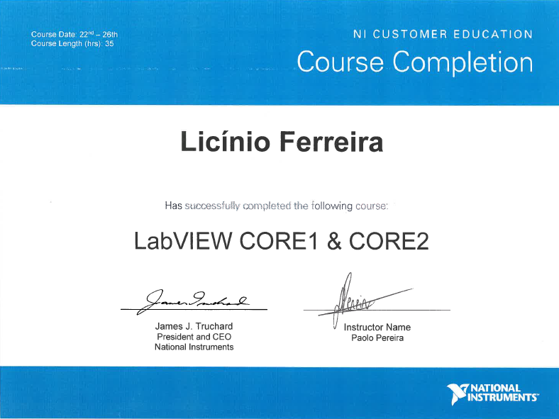
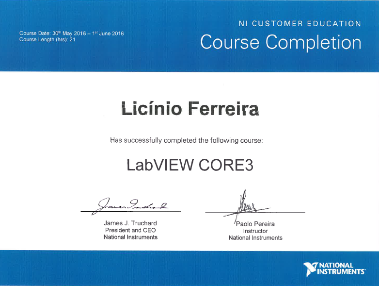
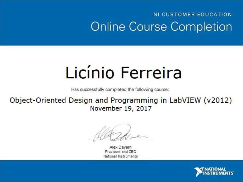
LabVIEW Core 1 & 2 – fundamentals and development practices.LabVIEW Core 3 – advanced architectures and performance.OOP in LabVIEW – classes, inheritance, dynamic dispatch.
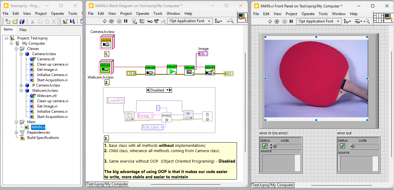
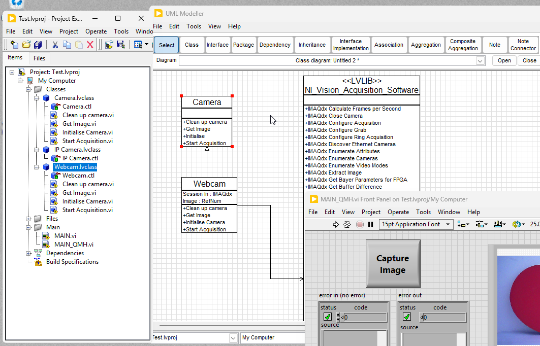
Mini Project: OOP Camera Abstraction
OOP architecture: base class + specialized webcam implementation.
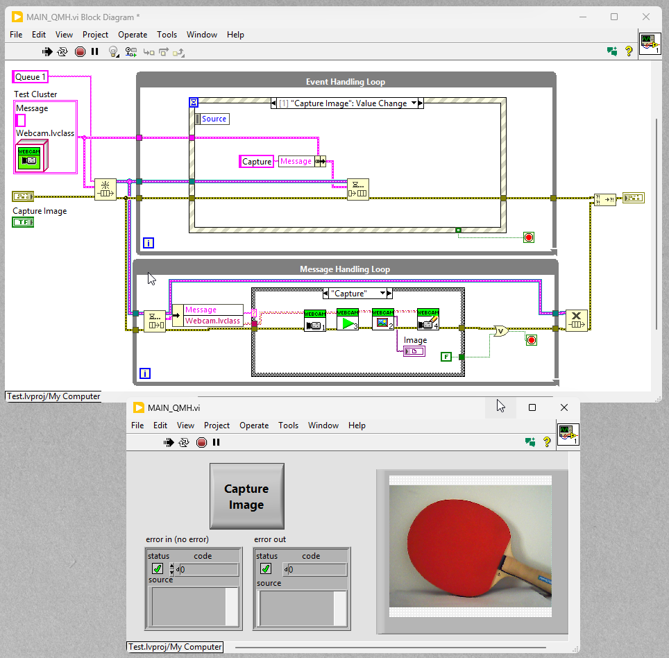
OOP QMH (Queue Message Handler) Camera App
UI events push commands to the queue.Message loop executes camera actions.
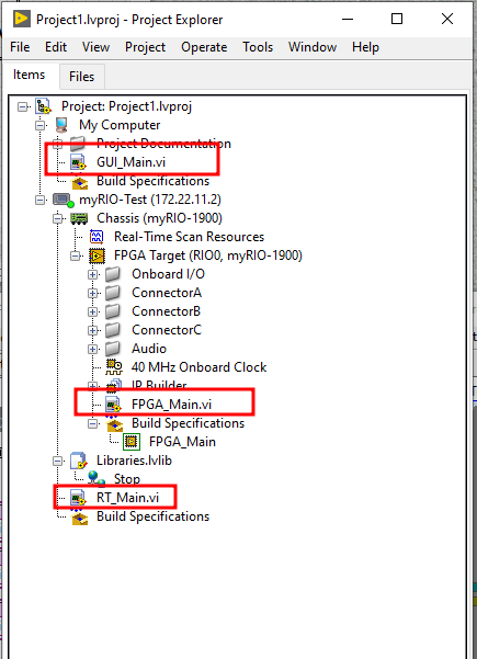
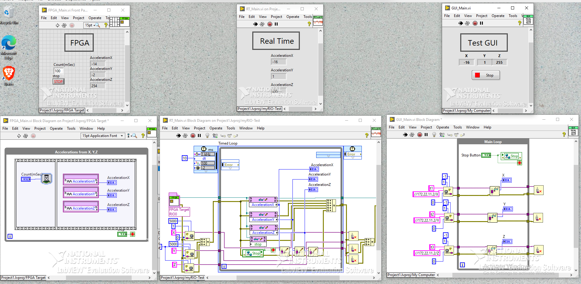
Mini Project: myRIO (FPGA + RT + GUI)
Front panel for real-time acquisition.Block diagram (RT + FPGA components).
Mini Project: myRIO (WebCAM + RT + GUI)
In this section shows another mini project using the LabVIEW Real Time (2018), a myRIO (1900), a webcamera and Windows 10.
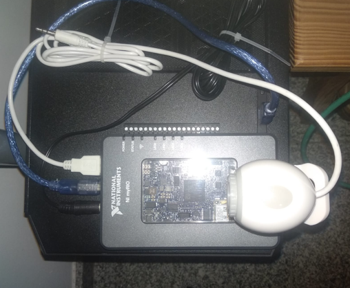
The main goal of this project is to capture a video stream coming from a webcamera that is connected to the myRIO via USB Port
(as is shown in the image below).
Setup test: PC, myRIO (1900) and webcamera (640x480 resolution).
GUIs (Real Time and User levels)
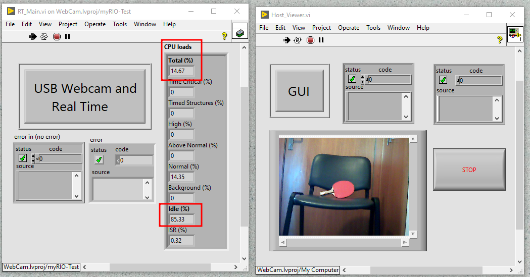
The image below shows two GUIs (from Target and Host), displaying the serveral indicators, as the CPU load (from myRIO) and
the real-time stream video to the User Interface (Host).
GUIs in Real-Time Systems
Real Time in LabVIEW
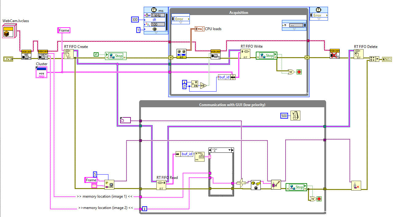
The architecture is divided into two parallel execution loops, each with a specific function and a different execution priority.
1. The Producer Loop: "Acquisition" (High Priority)
This loop is the data producer. Its single and most critical function is to capture frames from the webcam and pass them to the
consumer loop, without interruptions and as fast as possible.
WebCam.lvclass Block: This is the object or class that represents the webcam. It is configured to capture image frames and extract
information such as the data cluster and the capture time (dt).
RT FIFO Create: This block creates a Real-Time FIFO. A FIFO is a circular memory buffer. The RT (Real-Time)
concept indicates that this buffer is optimized for real-time systems, ensuring that data writing and reading are predictable and
not subject to operating system delays, for example Windows. It acts as the communication between the two loops.
RT FIFO Write: This block is the motor of the producer loop. It takes the captured image frame and writes it into the FIFO buffer.
The writing is a high-priority operation and is optimized to be as fast as possible.
Stop Control: The loop continues to write frames until a stop condition - Stop button is triggered by the user.
2. The Consumer Loop: "Communication with GUI" (Low Priority)
This loop is the data consumer and its function is to read frames from the FIFO buffer and perform other lower-priority operations, such as displaying them on the screen.
RT FIFO Read: This block reads the frames that were written by the producer loop.
Block diagram - Real Time system (Target).
GUI in LabVIEW
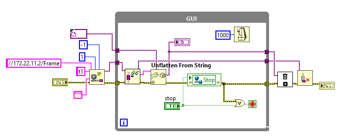
Block diagram - User Interface (Host).
Mini Project: Invoking a DLL file in LabVIEW
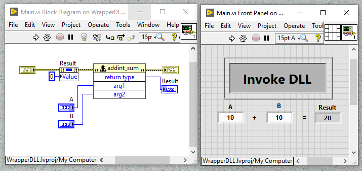
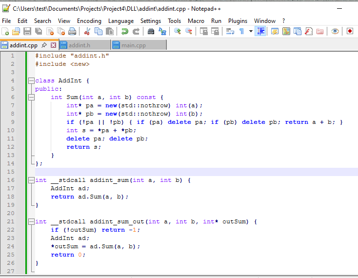
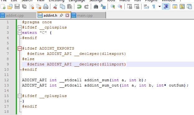
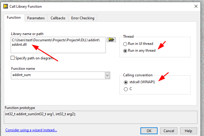
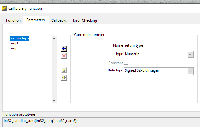
DLL file in LabVIEW.Source code in C++ - implementation fileSource code in C++ - header file.
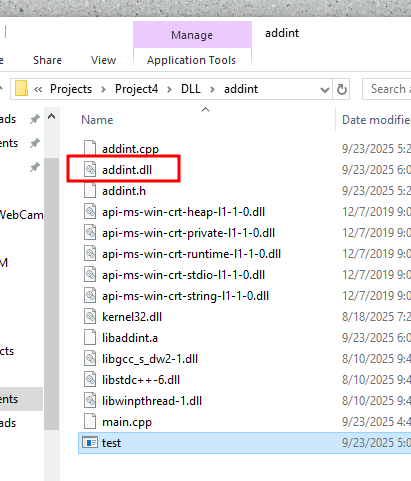
Command: g++ -shared -DADDINT_EXPORTS -o addint.dll addint.cpp "-Wl,--out-implib,libaddint.a,--add-stdcall-alias" -static-libstdc++ -static-libgcc
All files in the same directory: DLL, header and implementation filesAdding the DLL file in LabVIEWDefine the parameters of the library